Innovative reversible separation in distillation
Reinventing fluid separations to achieve high eco-efficiency
Distillation has a thermodynamic efficiency of only 10-12%, due to the degradation of energy associated to the temperature difference between the reboiler and condenser, and the mixing of liquid streams of different compositions on each stage.[1][2]
RevSep is a new concept; it has a higher thermodynamic and thermal efficiency, by near diabatic reversible separation. The basic element is the horizontal layout, thermal integration and the use of a reversible energy cycle. Fractional condensation and vaporization are included to enhance the separation. Overall energy savings of 90% are possible.
Diabatic operation
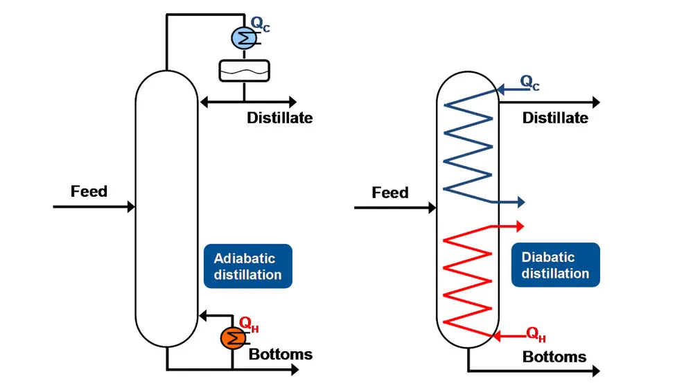
Gradual heat transfer (i.e. diabatic operation) can solve this problem but it requires large CAPEX, with many heat exchangers placed along the column.[3][4] Alternative solutions involve heat pumps (such as mechanical vapor recompression, or internally heat integrated distillation columns) but they require expensive compression. These are expensive energy saving technologies with long payback times.[5] In contrast to adiabatic distillation, a diabatic column replaces the reboiler and the condenser with integrated heat exchangers allowing gradual supply and removal of the heat along the rectification and stripping sections, respectively (see Figure 1). Heat transfer takes place at lower temperature differences that imply smaller exergy losses associated with the heat transfer.
RevSep technology
RevSep technology allows a reversible separation. Its configuration has a closed thermal cycle, with a hot and cold end.[6] The cold part of the cycle is in the upper section of the horizontal column, while the hot part is in the lower part. A packing section is used between the lower and upper sections to enhance the separation. A binary mixture (liquid) is fed in the lower section (reboiling) to operate at total reflux. Vaporization in the bottom section is followed by condensation in the top section, gradually resulting in a dynamic equilibrium of the heavy key (HK) component at the hot end and the light key (LK) component at the cold end. With pinching temperatures at both ends, just a small amount of energy is sufficient to maintain a dynamic equilibrium driving force and the subsequent separation of the binary mixture.
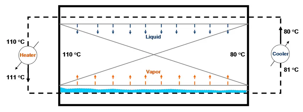
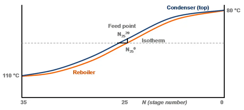
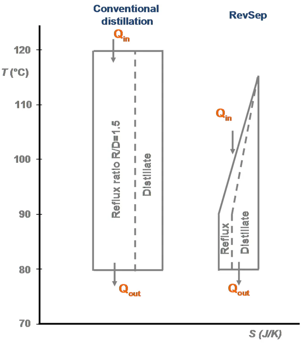
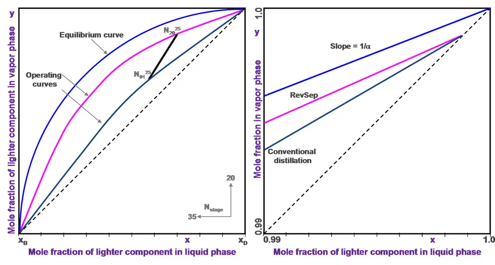
Figure 2 shows the operation conditions for the binary mixture benzene (LK) / toluene (HK), while Figure 3 shows the temperature profile along the RevSep, and Figure 4 illustrates the temperature-entropy diagram. The reversible energy cycle is able to separate a binary mixture and maintain the equilibrium conditions. Note that this is a total reflux operation to demonstrate the basic idea of the separation. The ratios of the heat required and generated by the cycle are related as pinching temperature differential and the difference of the temperature of the HK and LK.
This is equal to the ratio between the duties of the reboiler and the heater, or the ratio between the temperature difference on the reboiler (ΔTr) and the one on the heater (ΔTh). In the case shown above this ratio is 30/1. The load of the internal reflux (L) is determined by the initial slope of the equilibrium line (1/α, where α is the relative volatility). In this case the ratio of reflux to vapor boil-up L/V = 1/2.5 = 0.4, meaning that for each mol evaporated the internal reflux amounts to 0.4 mol (which is less than in case of conventional distillation where L/V=0.6).
Thermodynamically, the amount of work to separate any (ideal) binary mixture at temperature T is expressed as W=T×dS. For conventional distillation, the real amount of work W* is around 10-15 % of W.[7] When heat (Q) is used then: W* = (T-T’)/T × Q. For conventional distillation of B/T heat is added to the reboiler and (T-T’) is at least 45 °C. In the RevSep situation, heat is added in between the bottom and feed point so (T-T’) is 16 °C. Considering a modest reduction of the heat, the amount of work W* will be improved to about 40-50%.
A major advantage is that a RevSep unit operates at low liquid loads for the majority of cases
Operating mode of RevSep
Figure 5 schematically shows a RevSep unit, which consist of four sections, one above the other: 1 Reboiling | 2 Fractional evaporation | 3 Packing | 4 Fractional/partial condensation. The bottom section carries out the reboiling of the liquid feed and internal reflux. Above a section of fractional evaporation of the internal reflux and liquid feed by means of multiple feed points. Third section is provided with wire mesh for the vapour / liquid contact from the sections above and below. At the top is the condenser section, where the tubular bundle is extended with wire mesh packing to enhance the separation. It operates as partial / fractional condenser of the vapour leaving the packing section. The cycle provides a total reflux condition that serves the necessary reflux downstream of the feed point and reboiling upstream of the feed point.
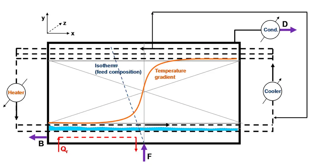
Figure 6 shows a comparison between RevSep and conventional distillation by means of a McCabe-Thiele diagram. The line N0125-N2025 is the vertical direction above the feed point. In the x-direction there are 35 stages and the y-direction there are 20 stages, thus a total of 700 stages. The area in between contains the other locus. Note that the slope of the equilibrium line is shown at high concentration and can be considered as a straight line. The same applies for the operating lines. The slope of the operating lines is slightly diverted from the equilibrium line. This is to demonstrate the difference as compared to conventional distillation.
At normal operation, the saturated feed stream (F) enters the bottom part of the unit, see Figure 5. The distillate (D) of LK is withdrawn at the top of the cold end and condensed in an external cooler. The liquid phase bottom (B) product consisting of HK exits the reboiling section at the bottom of the hot end. The temperature profile is characterized by a sinus shape with almost isothermal shape at both ends. The heat to generate the energy for the LK distillate is added in between the bottom hot end and the feed point. The energy to balance the equilibrium vapor flow above the feed point can be added to the cycle’s heater or a separate heater. The same applies for the cold end where additional cooling is foreseen in the top section. This cooling can be a separate one or it can be included in the cycle. The cycle is heated and cooled externally. The problem of the exergy losses in the cycle can be partially solved as follows:
- between feed point and bottom exit, reboiling is carried out by the heat required for the distillate and the equilibrium amount of vapor,
- the fractional evaporation is carried out by the cycle, the temperature of the cycle becomes lower when passing the feed point.
After passing the feed point the cycle takes care of the reboiling and the fractional evaporation. The same applies for the condenser section. The reboiling is carried out in discrete steps, as baffles are located in the disengaging area between tubes of the reboiling section and the next layer of tubes in the fractional vaporisation section. The mass of the liquid flow travelling to the exit increases (at the outlet becoming equal to the bottom product) and is not subject in mixing with vapor.
The second section consists of a tubular bundle provided with wire mesh packing and a certain number of feed points. The drawing in Figure 5 indicates a tubular section of the cycle in the liquid phase of the reboiling section and a tubular section above for the fractional evaporation. In reality the fractional evaporation section will contain more tubular sections, and each section can have its own feed point. The feed points are located with increasing height (y-direction) and inclination (x-direction), on the isotherm (feed composition). This improves the separation due to reduced mixing of vapour and liquid and minimises the liquid flow in the reboiling section. The vapour flow direction is in the y and x-direction and the composition increases in the LK.
The packing section contains high surface area wire mesh, where vapor exiting the fractional vaporisation section is in contact with the liquid from the condenser section. The RevSep unit operates in a rectifying mode with an overall L/V <1.0 (in the example L/V>0.4). The vapor flow direction is mainly in the y-direction and partially in the x-direction.
The condenser operates as a fractional and partial condenser. To enhance the separation a high-density wire mesh packing (BX) is used with the tubular bundle. The residual vapor flow leaving the condensing stage in the x-direction is richer in LK than the equilibrium condition of the liquid exiting the condenser to the packing. The composition and mass flow of the vapour passing the feed point is lower than the equilibrium condition at the feed point. The drag of the horizontal vapor flow causes liquid to carry over the feed point vertical. It is higher in LK than the feed. It further compensates the excess heat transferred by the cycle in the reboiling section.
The isotherm representing the feed composition is inclined in the y-direction, as shown in Figure 5. The cumulative vapor flow in the x-direction passing the vertical cross section at the liquid feed point is substantially lighter in LK. The difference in LK of this flow and the vapour, in equilibrium with the feed, represents a reduced mass flow and saving in thermal energy. This is a key difference with conventional distillation where the vapour flow composition is in equilibrium with the total mass flow of feed and reflux at the feed point. The bypass representing the thermal loss is arranged in such a way to reduce the exergy loss of the cycle in the condensing section. The largest part of the energy can be added in between bottom exit and feed point (by heat or compression), improving the thermodynamic efficiency. Note that with wide-boiling mixtures the focus is on thermodynamic efficiency and the design is easy, while with close-boiling mixtures the focus is on thermal efficiency and this requires operating data from a pilot unit.
The thermodynamic efficiency of the RevSep concept is at least 3 times higher compared to conventional distillation
Operation characteristics of RevSep
The layout of a RevSep unit can be a box type operating up to 3.5 bar, or column type for higher pressures, and can be operated in cryogenic service or above ambient temperatures. RevSep can handle binary mixtures, multi-component mixtures and presence of non-condensables. A major advantage is that it operates at low liquid loads (1-10 m³/hr/m²) for the majority of cases, even at high pressures. The wire mesh enables high mass transfer, low pressure drop and maintains liquid distribution by its capillarity characteristics and compact design. Liquid distribution requires uniformity only in the z-direction. The rearranged BX type wire mesh is used in the condensing section and in the evaporating section between the tubes and tube layers. Pressure drop of the vapor flow in the x-direction is in the range of 0.5 mbar/m. To cope with the pressure difference a slight tilt of the column of 0.1% is foreseen. It enables a smooth operation of the liquid flow in the reboiling section. The baffle spacing in the reboiling section is 100-150 mm to provide discrete separation stages. The number of stages is expected to be 5-7 per meter (HETP = 0.2-0.14 m), but 25-30% more separation stages are required in comparison with conventional distillation. The column length will be comparable with a packed column (BX type) but substantially shorter than a tray column.
Conclusions
The RevSep concept is a breakthrough innovation in separation technology, as the thermodynamic efficiency is at least 3 times higher (in the 40-50% range) compared to conventional distillation. The thermal efficiency is over 50%; further improvement in the thermal efficiency requires more reversible heat integration. Besides extending the tubular sections, a split flow of the cycle would be required. This is not economical for high alpha values, but it is for low alpha values.
The horizontal layout allows excellent heat integration, and the energy required for the separation at a lower level improves the thermodynamic efficiency. Fractional condensation and evaporation reduce the energy requirement and subsequently improves the thermal efficiency. This means reduced steam consumption and the use of steam at lower temperature and pressure. The capital costs may be higher than conventional distillation (depending on e.g. shop fabricated or field erected units and high or low alpha value mixtures), but the incremental cost is outweighed by the lower cost for utilities, leading to short payback times.
The economics for the separation of a binary mixture becomes more favorable with decreasing relative volatility (close boiling components). RevSep has a wide range of application (such as petrochemical, chemicals, oil and gas, air separation), and the impact on reducing the thermal energy used and CO2 emissions will be substantial (with up to 90% reduction, depending on the mixture separated).
Overall, the RevSep concept has substantial advantages to justify a pilot operation to obtain data to make an industrial design and to validate simulation models for further design improvements.
About the authors
John J. M. Gommers, Gommers Development Group, Prague. j.j.m.gommers@gommers.tech
Anton A. Kiss, Delft University of Technology, Faculty of Applied Sciences (TNW), Biotechnology & Chemical Engineering Dept. TonyKiss@gmail.com (corresponding author)